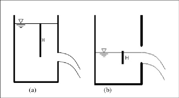
In the field of hydraulics and fluid mechanics, understanding the behavior of fluid flow through various types of orifices is fundamental to the design and analysis of many engineering systems. Among the different orifice configurations, the fully submerged orifice presents unique characteristics that distinguish it from partially submerged or free discharge orifices. A fully submerged orifice, also known as a drowned orifice, is defined as an opening where both the upstream and downstream liquid levels are above the top edge of the orifice.
This configuration creates a distinct flow pattern where the fluid discharges from a region of higher pressure to a region of lower pressure, both of which are below the surface of the liquid. The driving force for the flow is the difference in elevation between the two liquid surfaces, rather than the absolute height of the liquid column above the orifice. This makes the analysis of fully submerged orifices particularly important in applications such as underwater discharge systems, inter-compartment flow in ships, and various industrial processes.
Introduction to Fully Submerged Orifices
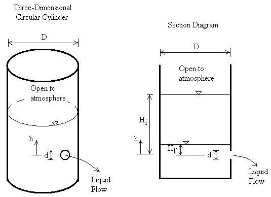
A fully submerged orifice is characterized by the condition that both the upstream and downstream water levels are above the top edge of the orifice opening. This means that the entire orifice is always covered by liquid, eliminating any free surface effects at the discharge point. This configuration is commonly encountered in underwater structures, ship ballast systems, and various industrial applications where controlled flow between two liquid-filled compartments is required.
The key distinguishing feature of a fully submerged orifice is that the flow is entirely enclosed by liquid on both sides, unlike partially submerged orifices where part of the orifice may be exposed to atmospheric pressure. This creates a more controlled flow environment but also introduces complexities in the analysis due to the pressure conditions on both sides of the orifice.
Some common applications of fully submerged orifices include:
- Flow between compartments in ship ballast tanks
- Underwater discharge systems in marine structures
- Sluice gates in dam structures
- Industrial processes involving liquid transfer between tanks
- Aquarium and water feature designs
Understanding the principles governing flow through fully submerged orifices is essential for engineers working in these fields, as incorrect assumptions about the flow behavior can lead to significant errors in system design and operation.
Effective Head in Fully Submerged Orifices
One of the most critical concepts in analyzing flow through fully submerged orifices is the determination of the effective head that drives the flow. Unlike free discharge orifices where the head is measured from the liquid surface to the center of the orifice, in fully submerged orifices, the driving force is the difference in elevation between the upstream and downstream liquid surfaces.
Let’s define:
- H₁ = Elevation of upstream liquid surface above a reference datum
- H₂ = Elevation of downstream liquid surface above the same reference datum
- H = Head difference = H₁ – H₂
The effective head H represents the potential energy difference per unit weight of fluid between the two surfaces. This head difference is the driving force for the flow through the orifice.
It’s important to note that this head difference is independent of the absolute elevations of the liquid surfaces and depends only on the relative difference between them. This characteristic makes fully submerged orifices useful in applications where maintaining a constant flow rate is desired despite changes in the absolute water levels.
The effective head concept also highlights why fully submerged orifices are sometimes referred to as “drowned” orifices – the downstream water level effectively “drowns” the orifice, preventing free discharge to the atmosphere.
Velocity and Discharge Formula
The analysis of flow through fully submerged orifices follows similar principles to other orifice types but with important modifications to account for the unique flow conditions. The theoretical velocity of the jet can be derived from Bernoulli’s equation, considering the energy balance between the two liquid surfaces.
Theoretical Velocity
Applying Bernoulli’s equation between the upstream liquid surface (point 1) and the downstream liquid surface (point 2), and neglecting losses, we get:
Where:
- v is the theoretical velocity of the jet
- g is the acceleration due to gravity
- H is the head difference between upstream and downstream surfaces
This equation is identical in form to Torricelli’s law for free discharge orifices, but with a different interpretation of the head term. Here, H represents the head difference rather than the height of liquid above the orifice.
Actual Velocity and Coefficient of Velocity
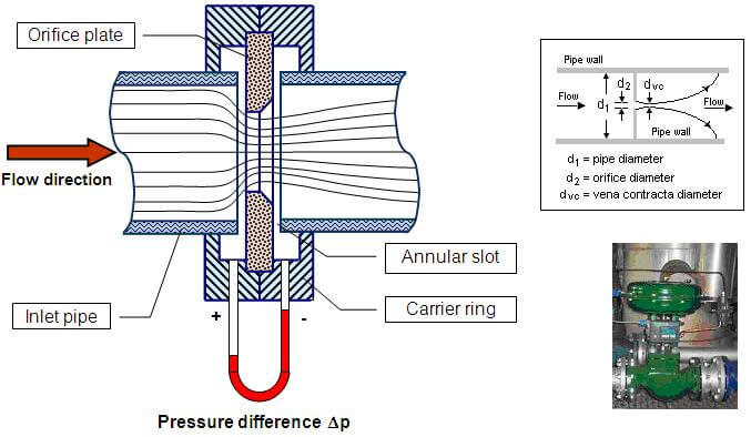
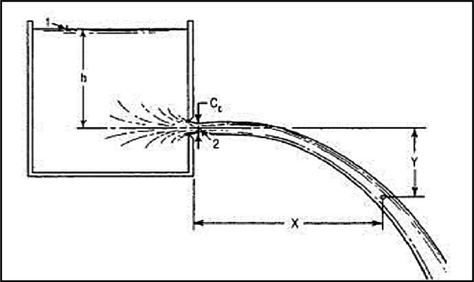
In practice, the actual velocity at the vena contracta (the point of minimum cross-sectional area in the jet) is less than the theoretical velocity due to various losses in the system. These losses include friction, turbulence, and the contraction of the jet as it exits the orifice.
The relationship between actual and theoretical velocity is expressed through the coefficient of velocity (Cᵥ):
The coefficient of velocity typically ranges from 0.95 to 0.99 for well-designed orifices, with the exact value depending on factors such as orifice shape, edge condition, and Reynolds number.
Area of Jet and Coefficient of Contraction
As the fluid exits the orifice, the jet contracts to a minimum cross-sectional area at the vena contracta. This phenomenon is quantified by the coefficient of contraction (C꜀), which is the ratio of the area of the jet at the vena contracta to the area of the orifice:
The coefficient of contraction typically ranges from 0.61 to 0.69 for sharp-edged orifices, with the exact value depending on the orifice geometry and flow conditions.
Actual Discharge Formula
Combining the effects of velocity and contraction, we can derive the formula for actual discharge through a fully submerged orifice:
Introducing the coefficient of discharge (C_d) as the product of the coefficient of velocity and the coefficient of contraction:
We arrive at the final discharge formula:
Where:
- Q is the actual discharge
- C_d is the coefficient of discharge
- A is the area of the orifice
- g is the acceleration due to gravity
- H is the head difference between upstream and downstream surfaces
This formula is remarkably similar to that for free discharge orifices, with the key difference being the interpretation of the head term H. The coefficient of discharge for fully submerged orifices typically ranges from 0.58 to 0.65, depending on the specific conditions.
Factors Affecting Flow Through Fully Submerged Orifices
Several factors influence the flow characteristics and discharge coefficient of fully submerged orifices. Understanding these factors is crucial for accurate calculations and proper system design.
Orifice Geometry
The shape and dimensions of the orifice significantly affect the flow characteristics:
- Circular orifices: Most common and well-studied shape, with predictable contraction characteristics
- Rectangular orifices: Common in sluice gates and control structures, with different contraction patterns
- Sharp-edged vs. rounded orifices: Sharp edges produce more pronounced contraction, while rounded edges reduce contraction and losses
Reynolds Number Effects
The Reynolds number, which characterizes the flow regime, affects the discharge coefficient:
Where:
- v is the velocity
- D is a characteristic length (orifice diameter for circular orifices)
- ν is the kinematic viscosity of the fluid
At low Reynolds numbers (laminar flow), the coefficient of discharge may vary significantly with flow rate. At high Reynolds numbers (turbulent flow), the coefficient tends to stabilize at a relatively constant value.
Proximity Effects
The proximity of the orifice to boundaries can significantly affect the flow:
- Side walls: Close proximity to side walls can reduce contraction on those sides
- Bottom and top boundaries: Similar effects occur near the bottom and top of the orifice
- Approach channel geometry: The shape and size of the upstream approach channel affects the velocity distribution
Submergence Ratio
The ratio of downstream submergence to orifice dimensions can affect the flow pattern:
Very low submergence ratios can lead to surface effects that invalidate the fully submerged assumption.
Sample Problem
Let’s work through a practical example to illustrate the application of these principles. Consider a rectangular sluice gate in a dam structure with the following characteristics:
- Orifice width (B) = 4 meters
- Orifice height (h) = 1.5 meters
- Upstream water level above sill = 5.0 meters
- Downstream water level above sill = 3.2 meters
- Coefficient of discharge (C_d) = 0.62
- Acceleration due to gravity (g) = 9.81 m/s²
Step 1: Determine the Head Difference
The head difference between upstream and downstream surfaces is:
Step 2: Calculate the Orifice Area
For a rectangular orifice:
Step 3: Apply the Discharge Formula
Using the formula for discharge through a fully submerged orifice:
Substituting the values:
Calculate the terms step by step:
Therefore, the discharge through the sluice gate is 22.14 cubic meters per second.
Verification and Sensitivity Analysis
Let’s verify our result by checking if the orifice is indeed fully submerged:
- Top of orifice above sill = 1.5 meters
- Upstream water level above sill = 5.0 meters (> 1.5 meters)
- Downstream water level above sill = 3.2 meters (> 1.5 meters)
Since both water levels are above the top of the orifice, our assumption of fully submerged conditions is valid.
Let’s also examine how sensitive our result is to changes in the coefficient of discharge. If C_d varies by ±5%:
- For C_d = 0.589 (5% lower): Q = 21.03 m³/s
- For C_d = 0.651 (5% higher): Q = 23.25 m³/s
This shows that a 5% change in the coefficient of discharge results in approximately a 5% change in discharge, highlighting the importance of accurate coefficient determination.
Applications in Engineering
The principles of flow through fully submerged orifices have numerous practical applications across various engineering disciplines:
Ship Ballast Systems
In maritime engineering, fully submerged orifices are commonly used in ship ballast systems to control the flow of water between ballast tanks. These systems must operate reliably under various sea conditions, making accurate flow prediction essential for proper system design.
Typical design considerations for ballast systems include:
- Ensuring adequate flow rates for efficient ballasting and de-ballasting
- Preventing excessive flow velocities that could cause structural damage
- Accounting for the effects of ship motion on flow characteristics
Dam and Reservoir Structures
Sluice gates and outlet works in dams and reservoirs often operate as fully submerged orifices, particularly during high water levels. Engineers use these principles to design systems that can safely pass flood flows while maintaining control over water levels.
Key design aspects include:
- Sizing gates for required discharge capacities
- Ensuring adequate submergence to maintain fully submerged conditions
- Providing adequate structural support for gate forces
Industrial Process Systems
Many industrial processes involve the transfer of liquids between tanks or vessels under controlled conditions. Fully submerged orifices provide a simple and effective means of controlling these flows.
Applications include:
- Chemical processing plants for controlled reagent addition
- Water treatment facilities for process water transfer
- Food and beverage production for ingredient metering
Aquaculture and Water Feature Design
In aquaculture systems and decorative water features, fully submerged orifices are used to create controlled circulation patterns and maintain water quality.
Design considerations include:
- Providing adequate circulation for oxygen transfer
- Preventing dead zones where water stagnates
- Controlling flow velocities to prevent erosion or disturbance of aquatic life
Comparison with Other Flow Conditions
Understanding how fully submerged orifices compare with other flow conditions helps engineers select the appropriate analysis method and design approach:
| Flow Condition | Characteristics | Driving Head | Discharge Formula | Typical Applications |
|---|---|---|---|---|
| Fully Submerged | Both surfaces above orifice | Difference in surface elevations | Q = C_d × A × √(2gH) | Sluice gates, ballast systems |
| Partially Submerged | One surface above, one below orifice | Combination of both heads | Q = Q₁ + Q₂ | Variable head conditions |
| Free Discharge | Downstream surface below orifice | Upstream head above orifice | Q = C_d × A × √(2gH) | Overflow weirs, drainage |
While the basic discharge formula appears similar for fully submerged and free discharge orifices, the interpretation of the head term H is fundamentally different, leading to different design considerations and applications.
Advanced Considerations
For more complex applications or high-precision requirements, engineers may need to consider additional factors that affect the flow through fully submerged orifices:
Unsteady Flow Effects
In situations where the upstream or downstream water levels are changing rapidly, unsteady flow effects become important. These effects can cause the actual discharge to differ from steady-state calculations, particularly during the initial stages of flow changes.
Unsteady flow analysis requires consideration of:
- The time rate of change of water levels
- The inertia of the flowing fluid
- The compressibility of the fluid (for high-velocity flows)
Scale Effects
When extrapolating results from model studies to full-scale prototypes, scale effects can be significant. These effects arise due to differences in Reynolds number and other dimensionless parameters between the model and prototype.
Scale effects are particularly important when:
- The Reynolds number in the model is significantly different from that in the prototype
- Surface tension effects are important (small scale models)
- The flow involves complex turbulence patterns
Temperature and Viscosity Effects
For applications involving fluids with varying temperature or non-Newtonian behavior, the effects of temperature and viscosity on flow characteristics must be considered.
Important considerations include:
- Variation of fluid density with temperature
- Changes in kinematic viscosity affecting Reynolds number
- Non-Newtonian behavior in certain industrial fluids
Cavitation Considerations
In high-velocity flows or applications with significant pressure variations, cavitation may occur when the local pressure drops below the vapor pressure of the fluid. This can cause damage to system components and affect flow characteristics.
Cavitation prevention requires:
- Maintaining adequate pressure margins above vapor pressure
- Using appropriate materials resistant to cavitation damage
- Designing smooth flow transitions to minimize pressure fluctuations
Measurement and Control
Accurate measurement and control of flow through fully submerged orifices is important for many applications:
Flow Measurement
Fully submerged orifices can be used as primary elements in flow measurement systems. The relationship between head difference and discharge allows for indirect flow measurement by monitoring water levels.
Key considerations for flow measurement include:
- Accurate determination of the coefficient of discharge
- Proper installation of level measurement devices
- Regular calibration to account for changes in orifice condition
Flow Control
In control applications, fully submerged orifices can provide relatively stable flow characteristics as long as the submergence conditions are maintained. This makes them suitable for applications requiring consistent flow rates.
Control strategies may include:
- Adjustable orifices with variable opening areas
- Multiple orifices that can be selectively opened or closed
- Combination with upstream or downstream control structures
Conclusion
The analysis of flow through fully submerged orifices represents a fundamental aspect of hydraulic engineering with wide-ranging applications. By understanding that the driving force for flow is the difference in elevation between upstream and downstream liquid surfaces, engineers can accurately predict discharge rates using the established formula Q = C_d × A × √(2gH).
The sample problem demonstrates the practical application of these principles and shows how relatively straightforward calculations can provide valuable design information. The importance of accurate coefficient determination is highlighted by the sensitivity analysis, which shows that small changes in the coefficient can lead to proportionate changes in calculated discharge.
The diverse applications of fully submerged orifices, from ship ballast systems to dam outlet works, underscore their importance in engineering practice. The comparison with other flow conditions helps engineers understand when this analysis method is appropriate and when alternative approaches may be needed.
For complex applications, engineers must consider advanced factors such as unsteady flow effects, scale effects, and cavitation potential. These considerations are particularly important in high-consequence applications where flow prediction accuracy is critical.
As engineering systems become more complex and operating conditions more challenging, the fundamental principles of fully submerged orifice flow remain essential tools for analysis and design. Modern computational methods and measurement techniques continue to enhance our understanding and application of these principles, enabling more efficient and reliable hydraulic systems.
Future developments in materials science, computational fluid dynamics, and sensor technology will likely provide even more accurate methods for predicting and controlling flow through fully submerged orifices, further expanding their utility in engineering applications.