In the field of engineering mechanics and structural analysis, understanding the stress distribution in thin-walled pressure vessels is fundamental to the safe and efficient design of numerous engineering components. Among the various geometries of pressure vessels, spherical shells represent one of the most efficient configurations for containing internal pressure due to their uniform stress distribution and optimal strength-to-weight ratio.
Thin-walled spherical shells are commonly encountered in engineering applications such as LPG tanks, storage vessels for compressed gases, pressure vessels in chemical processing plants, and even in aerospace applications like fuel tanks and habitat modules. The analysis of stress in these structures is crucial for ensuring structural integrity while minimizing material usage and weight.
Introduction to Thin-Walled Spherical Shells
A thin-walled spherical shell is a pressure vessel with a spherical geometry where the wall thickness is significantly smaller than the radius of the sphere. The “thinness” of the shell is a critical assumption that simplifies the stress analysis by allowing us to assume uniform stress distribution through the wall thickness.
The definition of a “thin” shell is typically based on the ratio of the radius to the wall thickness. A commonly used criterion is that a shell is considered thin if:
Where:
- r is the internal radius of the spherical shell
- t is the wall thickness of the shell
When this criterion is satisfied, the error introduced by assuming uniform stress through the wall thickness is typically less than 5%, which is acceptable for most engineering applications.
Spherical shells are particularly advantageous in pressure vessel design because they provide the most efficient stress distribution of all possible geometries. For a given internal pressure and volume, a spherical vessel requires the least amount of material compared to cylindrical or other shaped vessels.
Common Applications
Thin-walled spherical shells find extensive use in various engineering applications due to their structural efficiency and manufacturing advantages:
- LPG Storage Tanks: Large spherical tanks for storing liquefied petroleum gas at moderate pressures
- Chemical Processing Vessels: Reactors and storage tanks for chemicals under pressure
- Aerospace Applications: Fuel tanks, pressurized cabins, and habitat modules for spacecraft
- Nuclear Industry: Containment vessels and reactor pressure vessels
- Underwater Structures: Submersible hulls and underwater storage vessels
- Industrial Gas Storage: Tanks for compressed air, nitrogen, and other industrial gases
The spherical geometry is particularly favored in applications where weight is critical (such as aerospace) or where large volumes need to be contained at moderate pressures (such as LPG storage).
Force Analysis
To understand the stress distribution in a thin spherical shell, we need to analyze the forces acting on the structure when it is subjected to internal pressure. This analysis is based on the principle of equilibrium and involves considering the forces acting on a portion of the shell.
Bursting Force Due to Internal Pressure
When a spherical shell is subjected to internal pressure, the pressure acts uniformly on the internal surface of the shell, creating a force that tends to expand the shell. To analyze this force, consider cutting the sphere in half along any diametral plane.
The internal pressure p acts on the projected circular area of the hemispherical cap. The bursting force can be calculated as:
Where:
- F_burst is the total bursting force acting on the hemispherical cap
- p is the internal pressure
- r is the internal radius of the spherical shell
This force acts perpendicular to the cut surface and tends to separate the two hemispherical portions of the shell.
Resisting Force in the Material Wall
The material of the shell wall resists the bursting force through internal stresses. To calculate the resisting force, we need to consider the stress distribution in the wall.
In a thin spherical shell, the stress is assumed to be uniformly distributed through the wall thickness and acts tangentially to the shell surface. This stress, known as the hoop stress or membrane stress, acts in all directions due to the spherical symmetry.
The resisting force can be calculated by considering the cross-sectional area of the wall around the circumference of the cut:
Where:
- F_resist is the total resisting force provided by the shell wall
- σ is the stress in the shell wall (to be determined)
- r is the internal radius of the spherical shell
- t is the wall thickness
Note that we use the internal radius r in this analysis, which is acceptable for thin shells where the difference between internal and external radii is small.
Derivation of Stress Formula
To derive the formula for stress in a thin spherical shell, we apply the principle of equilibrium by equating the bursting force and the resisting force.
Equilibrium Condition
For the hemispherical cap to be in equilibrium, the bursting force must equal the resisting force:
Substituting the expressions we derived:
Solving for Stress
Solving for the stress σ:
Simplifying by canceling common terms:
This is the fundamental formula for stress in a thin-walled spherical shell subjected to internal pressure.
Final Stress Formula
The stress in a thin-walled spherical shell is given by:
Where:
- σ is the stress in the shell wall (same in all directions due to symmetry)
- p is the internal pressure
- r is the internal radius of the spherical shell
- t is the wall thickness
Physical Interpretation and Characteristics
The derived stress formula for thin spherical shells has several important characteristics and physical interpretations that are crucial for engineering applications.
Uniform Stress Distribution
One of the most significant characteristics of spherical shells is that the stress is uniform in all directions along the shell’s surface. This is a direct consequence of the spherical symmetry:
- Isotropic Stress: The stress has the same magnitude in all tangential directions
- No Directional Preference: Unlike cylindrical shells, there is no distinction between hoop and longitudinal stresses
- Optimal Load Distribution: The uniform stress distribution makes spherical shells structurally efficient
Stress Proportionality
The stress formula reveals important proportional relationships:
- Directly Proportional to Pressure: Doubling the pressure doubles the stress
- Directly Proportional to Radius: Doubling the radius doubles the stress
- Inversely Proportional to Thickness: Doubling the thickness halves the stress
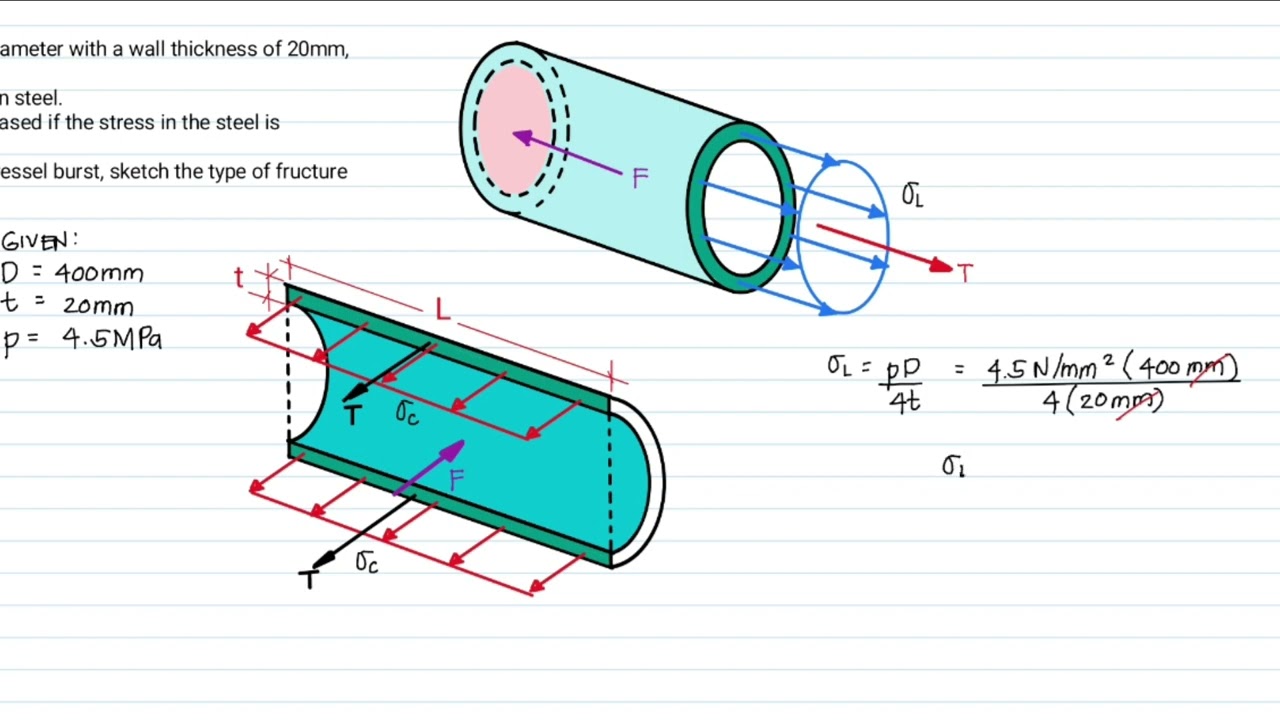
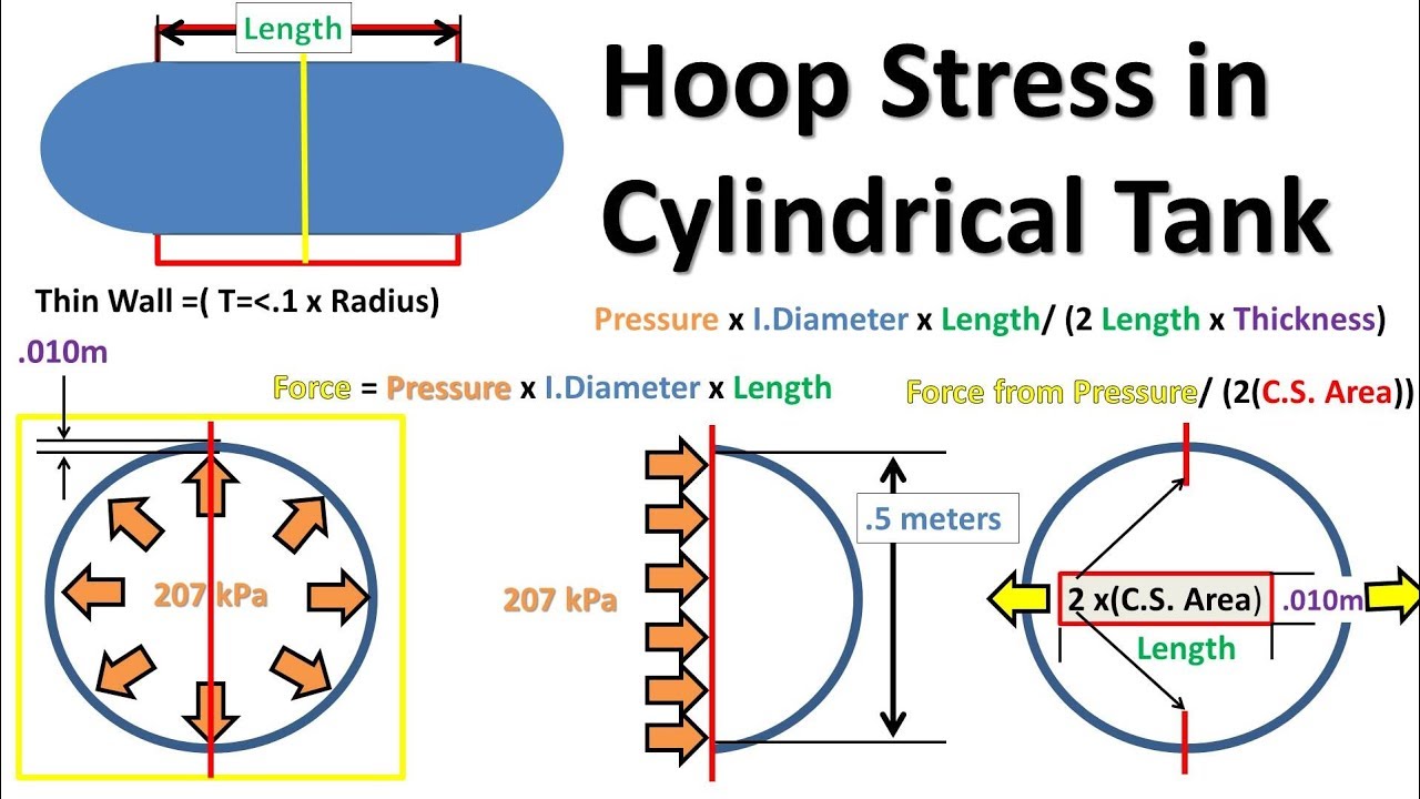
Comparison with Cylindrical Shells
Comparing spherical shells with cylindrical shells of the same radius and thickness:
- Spherical Shell Stress: σ = pr/(2t)
- Cylindrical Shell Hoop Stress: σ_hoop = pr/t
- Cylindrical Shell Longitudinal Stress: σ_long = pr/(2t)
This comparison shows that for the same pressure, radius, and thickness:
- Spherical shell stress = Cylindrical shell longitudinal stress
- Spherical shell stress = Half of cylindrical shell hoop stress
This explains why spherical vessels are more efficient for containing pressure – they experience lower maximum stresses than cylindrical vessels.
Sample Problems and Calculations
Let’s work through some sample problems to illustrate the application of the stress formula for thin spherical shells.
Problem 1: Basic Stress Calculation
A spherical pressure vessel has an internal diameter of 2 meters and a wall thickness of 10 mm. If the vessel contains gas at a pressure of 1.5 MPa, calculate the stress in the vessel wall.
Given:
- Internal diameter D = 2 m, so internal radius r = 1 m
- Wall thickness t = 10 mm = 0.01 m
- Internal pressure p = 1.5 MPa = 1.5 × 10⁶ Pa
Solution:
First, check if the thin shell criterion is satisfied:
The thin shell assumption is valid.
Using the stress formula:
Therefore, the stress in the vessel wall is 75 MPa.
Problem 2: Thickness Design
A spherical tank with an internal radius of 1.5 m is to contain a gas at a maximum pressure of 2 MPa. If the allowable stress in the tank material is 120 MPa, determine the minimum required wall thickness.
Given:
- Internal radius r = 1.5 m
- Internal pressure p = 2 MPa = 2 × 10⁶ Pa
- Allowable stress σ_allow = 120 MPa = 120 × 10⁶ Pa
Solution:
Rearranging the stress formula to solve for thickness:
Substituting values:
Therefore, the minimum required wall thickness is 12.5 mm.
Note: In practice, additional factors such as safety factors, corrosion allowances, and manufacturing tolerances would be considered.
Problem 3: Pressure Rating
A spherical pressure vessel has an internal diameter of 3 m and a wall thickness of 15 mm. If the material has an allowable stress of 150 MPa, what is the maximum internal pressure the vessel can safely contain?
Given:
- Internal diameter D = 3 m, so internal radius r = 1.5 m
- Wall thickness t = 15 mm = 0.015 m
- Allowable stress σ_allow = 150 MPa = 150 × 10⁶ Pa
Solution:
Rearranging the stress formula to solve for pressure:
Substituting values:
Therefore, the maximum safe internal pressure is 3 MPa.
Design Considerations
When designing spherical pressure vessels, several important factors must be considered beyond the basic stress calculations.
Safety Factors
Engineering design requires incorporating safety factors to account for uncertainties:
- Material Variability: Variations in material properties from batch to batch
- Manufacturing Tolerances: Variations in dimensions and quality
- Loading Uncertainties: Variations in operating conditions
- Environmental Effects: Corrosion, fatigue, and other degradation mechanisms
Typical safety factors for pressure vessels range from 2 to 4, depending on the application and relevant codes.
Material Selection
Material selection for spherical shells involves several considerations:
- Strength Properties: Yield strength and ultimate tensile strength
- Corrosion Resistance: Compatibility with the contained fluid
- Fabrication Characteristics: Weldability and formability
- Cost Considerations: Material cost and availability
- Temperature Effects: Performance at operating temperatures
Joint Design
Since large spherical vessels cannot be manufactured as single pieces, joints must be designed:
- Welded Joints: Most common for pressure vessels
- Bolted Joints: Used in some removable sections
- Joint Efficiency: Joints typically have lower efficiency than base material
- Inspection Requirements: Non-destructive testing of critical joints
Advanced Analysis Considerations
For more precise analysis or special applications, additional factors may need to be considered.
Thick Shell Analysis
When the r/t ratio is not sufficiently large, thick shell analysis is required:
- Lame’s Equations: Provide exact solutions for thick spherical shells
- Stress Variation: Stresses vary through the wall thickness
- Maximum Stress Location: Maximum stress occurs at the inner surface
Thermal Stresses
Temperature variations can induce additional stresses:
- Thermal Expansion: Differential expansion between shell and contents
- Temperature Gradients: Non-uniform temperature distribution
- Combined Loading: Interaction between pressure and thermal stresses
Dynamic Effects
Dynamic loading conditions require special consideration:
- Pressure Fluctuations: Cyclic pressure variations
- Impact Loads: Sudden pressure changes or external impacts
- Vibration Effects: Resonance and fatigue considerations
Comparison with Other Shell Geometries
Understanding how spherical shells compare with other geometries is important for design decisions.
| Shell Geometry | Stress Formula | Maximum Stress | Volume Efficiency | Manufacturing Complexity |
|---|---|---|---|---|
| Spherical | σ = pr/(2t) | pr/(2t) | Maximum for given surface area | High |
| Cylindrical | σ_hoop = pr/t σ_long = pr/(2t) |
pr/t | Moderate | Moderate |
| Rectangular | Complex – depends on aspect ratio | Higher than cylindrical | Low | Low |
Standards and Codes
The design of pressure vessels is governed by various codes and standards that ensure safety and reliability.
- ASME Boiler and Pressure Vessel Code: Primary code in North America
- EN 13445: European standard for unfired pressure vessels
- JIS B 8265: Japanese industrial standard for pressure vessels
- GB 150: Chinese standard for steel pressure vessels
These codes provide detailed requirements for design, materials, fabrication, inspection, and testing of pressure vessels.
Conclusion
The analysis of stress in thin-walled spherical shells is a fundamental topic in engineering mechanics that has wide-ranging applications in pressure vessel design. The simple yet powerful formula σ = pr/(2t) provides engineers with the essential tool for designing safe and efficient spherical pressure vessels.
The spherical geometry’s advantage of uniform stress distribution in all directions makes it the most structurally efficient shape for containing internal pressure. This efficiency is reflected in the fact that spherical shells experience only half the maximum stress of cylindrical shells under the same conditions.
The sample problems demonstrate the practical application of the stress formula in three common engineering scenarios: calculating stress for known geometry and pressure, determining required thickness for given loads, and establishing pressure ratings for existing vessels. These calculations form the foundation of pressure vessel design.
However, real-world design involves many additional considerations beyond the basic stress calculations. Safety factors, material selection, joint design, and compliance with relevant codes and standards are all critical aspects of practical pressure vessel design. The thin shell assumption itself has limitations that must be recognized and addressed when appropriate.
For applications where the thin shell criterion is not satisfied, more complex thick shell analysis using Lame’s equations becomes necessary. Similarly, thermal stresses, dynamic effects, and other loading conditions may require more sophisticated analysis techniques.
The comparison with other shell geometries highlights the trade-offs engineers must consider when selecting vessel shapes. While spherical shells are most efficient structurally, factors such as manufacturing complexity, space constraints, and connection requirements may favor other geometries.
Modern computational methods, including finite element analysis, have enhanced our ability to analyze complex geometries and loading conditions that go beyond the simple analytical solutions. However, the fundamental principles embodied in the thin spherical shell stress formula remain as important as ever for understanding and predicting structural behavior.
As engineering applications continue to demand higher pressures, more extreme temperatures, and greater reliability, the principles of stress analysis in spherical shells will continue to evolve. New materials, advanced manufacturing techniques, and improved analytical methods will enhance our ability to design even more efficient and reliable pressure vessels.
For students and practitioners of engineering mechanics, mastering the analysis of thin spherical shells provides a solid foundation for understanding more complex structural problems. The concepts of equilibrium, stress distribution, and material behavior illustrated by this simple geometry are applicable to a wide range of engineering structures and systems.
In conclusion, the stress analysis of thin-walled spherical shells represents a perfect example of how fundamental engineering principles can be applied to solve practical design problems. The combination of theoretical analysis, practical considerations, and real-world applications makes this topic both intellectually satisfying and professionally valuable.