In the field of mechanical engineering, helical springs are among the most commonly used mechanical elements for storing and releasing energy, providing force, and absorbing shocks. Understanding the behavior of these springs under load, particularly their deflection and stiffness characteristics, is fundamental to their proper design and application in various engineering systems.
Closed coil helical springs, also known as compression springs, are characterized by their closely spaced coils that touch each other when the spring is at rest. These springs are designed primarily to resist compressive forces and return to their original length when the load is removed. The analysis of deflection and stiffness in such springs involves understanding the complex stress and deformation patterns that occur when an axial load is applied.
Introduction to Closed Coil Helical Springs
A closed coil helical spring is a mechanical element made by winding a wire or bar into a helical shape with closely spaced coils. In the unloaded condition, the coils are in contact with each other, hence the term “closed coil.” These springs are specifically designed to carry axial compressive loads and are widely used in applications ranging from automotive suspension systems to mechanical watches.
The key geometric parameters that define a closed coil helical spring include:
- Wire Diameter (d): The diameter of the wire used to make the spring
- Mean Coil Diameter (D): The average diameter of the spring coils
- Number of Coils (n): The total number of active coils in the spring
- Free Length (L₀): The length of the spring when no external load is applied
- Material Modulus of Rigidity (G): The shear modulus of the spring material
When an axial load is applied to a closed coil helical spring, it deflects by compressing along its axis. The amount of deflection and the spring’s resistance to this deflection (stiffness) are critical parameters that determine the spring’s suitability for specific applications.
Key Parameters and Definitions
Before deriving the expressions for deflection and stiffness, it’s essential to clearly define the key parameters involved in the analysis of closed coil helical springs.
Geometric Parameters
- Wire Diameter (d): The diameter of the wire from which the spring is made, measured in meters or millimeters
- Mean Coil Diameter (D): The average diameter of the spring coils, calculated as the outside diameter minus the wire diameter, measured in meters or millimeters
- Mean Coil Radius (R): Half of the mean coil diameter (R = D/2)
- Number of Active Coils (n): The number of coils that actually contribute to the spring’s deflection under load
- Spring Index (C): The ratio of mean coil diameter to wire diameter (C = D/d)
Material Properties
- Modulus of Rigidity (G): Also known as the shear modulus, this property measures the material’s resistance to shear deformation, measured in Pascals (Pa) or Gigapascals (GPa)
- Young’s Modulus (E): The modulus of elasticity, which relates stress to strain in tension or compression
- Poisson’s Ratio (ν): The ratio of transverse strain to axial strain
Loading and Response Parameters
- Axial Load (P): The external force applied along the spring axis, measured in Newtons (N)
- Deflection (δ): The change in spring length under load, measured in meters or millimeters
- Stiffness (k): The force required to produce unit deflection, measured in N/m or N/mm
- Stress (τ): The internal resistance per unit area within the spring material, measured in Pascals (Pa)
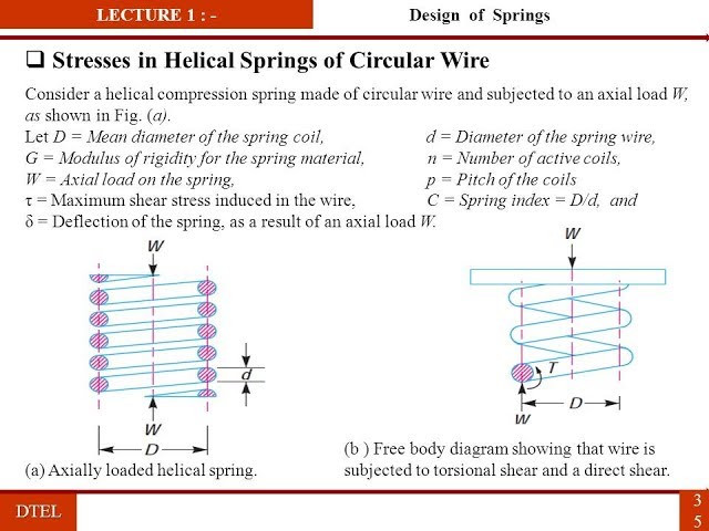
Analysis of Forces and Torques
To understand the behavior of a closed coil helical spring under axial load, we need to analyze the internal forces and torques that develop within the spring wire. This analysis forms the foundation for deriving expressions for deflection and stiffness.
Force Application
When an axial load P is applied to a closed coil helical spring, it creates a twisting moment (torque) on the wire. This occurs because the load is applied at the center of the spring, while the wire follows a helical path.
The torque T acting on the wire can be calculated as:
Where:
- T is the twisting moment (torque) on the wire
- P is the axial load applied to the spring
- R is the mean coil radius
- D is the mean coil diameter
Direct Shear Stress
In addition to the torsional effects, the axial load also creates direct shear stress in the wire. However, in basic analysis, this direct shear stress is often neglected because:
- The torsional stress is typically much larger than the direct shear stress
- The direct shear stress distribution is non-uniform across the wire cross-section
- For springs with a reasonable spring index (C > 4), the error introduced by neglecting direct shear is small
When more precise analysis is required, especially for springs with low spring indices, the direct shear stress can be included using appropriate correction factors.
Derivation Using Strain Energy or Torsion Formula
The deflection of a closed coil helical spring can be derived using either the strain energy method or the torsion formula. Both approaches yield the same result and provide insights into different aspects of the spring’s behavior.
Method 1: Using Torsion Equation
The torsion equation relates the applied torque to the resulting angular deflection:
Where:
- T is the applied torque
- J is the polar moment of inertia of the wire cross-section
- G is the modulus of rigidity of the material
- θ is the angular deflection (in radians)
- L is the length of the wire
For a circular wire cross-section, the polar moment of inertia is:
Where d is the wire diameter.
The length of the wire in the spring is:
Where:
- D is the mean coil diameter
- n is the number of active coils
Substituting these into the torsion equation:
Solving for θ:
Relating Angular Deflection to Axial Deflection
The angular deflection θ of the wire must be related to the axial deflection δ of the spring. This relationship is based on the geometry of the helical spring.
When the spring deflects axially by δ, the wire undergoes an angular deflection θ. The relationship between these quantities is:
Where R is the mean coil radius (R = D/2).
Substituting the expression for θ:
This is the fundamental expression for the deflection of a closed coil helical spring under axial load.
Method 2: Using Strain Energy
Alternatively, the deflection can be derived using Castigliano’s theorem, which relates deflection to the partial derivative of strain energy with respect to the applied load.
The strain energy U stored in the spring due to torsion is:
For a constant torque T along the length L:
Substituting T = PD/2, L = πDn, and J = πd⁴/32:
According to Castigliano’s theorem:
This confirms the same result obtained using the torsion method.
Final Expression for Deflection
Combining the results from both derivation methods, the final expression for the deflection of a closed coil helical spring is:
Where:
- δ is the axial deflection of the spring (m or mm)
- P is the axial load applied to the spring (N)
- D is the mean coil diameter (m or mm)
- n is the number of active coils (dimensionless)
- G is the modulus of rigidity of the spring material (Pa or MPa)
- d is the wire diameter (m or mm)
This equation shows that:
- Deflection is directly proportional to the applied load P
- Deflection is directly proportional to the cube of the mean coil diameter D³
- Deflection is directly proportional to the number of coils n
- Deflection is inversely proportional to the modulus of rigidity G
- Deflection is inversely proportional to the fourth power of the wire diameter d⁴
Derivation of Stiffness
Spring stiffness, also known as spring rate or spring constant, is defined as the force required to produce unit deflection. It is a fundamental parameter that characterizes a spring’s resistance to deformation.
Definition of Stiffness
Stiffness is defined as:
Where:
- k is the spring stiffness (N/m or N/mm)
- P is the applied load (N)
- δ is the resulting deflection (m or mm)
Deriving Stiffness from Deflection Formula
Using the deflection formula δ = (8PD³n)/(Gd⁴), we can derive the stiffness:
Simplifying by canceling P:
This is the fundamental expression for the stiffness of a closed coil helical spring.
Final Stiffness Formula
The stiffness of a closed coil helical spring is given by:
Where:
- k is the spring stiffness (N/m or N/mm)
- G is the modulus of rigidity of the spring material (Pa or MPa)
- d is the wire diameter (m or mm)
- D is the mean coil diameter (m or mm)
- n is the number of active coils (dimensionless)
This equation shows that:
- Stiffness is directly proportional to the modulus of rigidity G
- Stiffness is directly proportional to the fourth power of the wire diameter d⁴
- Stiffness is inversely proportional to the cube of the mean coil diameter D³
- Stiffness is inversely proportional to the number of coils n
Sample Problems and Calculations
Let’s work through some sample problems to illustrate the application of the deflection and stiffness formulas for closed coil helical springs.
Problem 1: Basic Deflection and Stiffness Calculation
A closed coil helical spring is made from a steel wire with the following specifications:
- Wire diameter (d) = 5 mm
- Mean coil diameter (D) = 50 mm
- Number of active coils (n) = 10
- Modulus of rigidity (G) = 80 GPa = 80 × 10⁹ Pa
Calculate:
- The stiffness of the spring
- The deflection when a load of 200 N is applied
Solution:
1. Calculating stiffness using k = Gd⁴/(8D³n):
2. Calculating deflection using δ = P/k:
Alternatively, using δ = (8PD³n)/(Gd⁴):
Therefore:
- Spring stiffness k = 5 N/mm
- Deflection δ = 40 mm under 200 N load
Problem 2: Design for Required Stiffness
Design a closed coil helical spring from steel (G = 80 GPa) that has a stiffness of 8 N/mm. The available wire diameters are 4 mm, 5 mm, and 6 mm. The mean coil diameter should be 8 times the wire diameter. Determine the required wire diameter and number of coils.
Given:
- Required stiffness k = 8 N/mm = 8,000 N/m
- G = 80 GPa = 80 × 10⁹ Pa
- D = 8d (mean coil diameter is 8 times wire diameter)
Solution:
Using the stiffness formula k = Gd⁴/(8D³n) and substituting D = 8d:
Solving for n:
Testing each wire diameter:
For d = 4 mm = 4 × 10⁻³ m:
For d = 5 mm = 5 × 10⁻³ m:
For d = 6 mm = 6 × 10⁻³ m:
All three options are feasible. The selection would depend on other design considerations such as space constraints, stress levels, and manufacturing preferences.
Problem 3: Load-Deflection Relationship
A spring has the following characteristics:
- Wire diameter d = 6 mm
- Mean coil diameter D = 60 mm
- Number of coils n = 8
- Material modulus of rigidity G = 79 GPa
Determine:
- The spring stiffness
- The deflection under loads of 100 N, 200 N, and 300 N
- The load required for a deflection of 25 mm
Solution:
1. Calculating stiffness:
2. Calculating deflections:
3. Calculating load for 25 mm deflection:
Factors Affecting Spring Performance
Several factors influence the performance and behavior of closed coil helical springs beyond the basic geometric and material parameters.
Spring Index Effects
The spring index (C = D/d) significantly affects spring performance:
- Low Index (C < 4): Difficult to manufacture, high stress concentrations
- Moderate Index (4 < C < 12): Optimal range for most applications
- High Index (C > 12): Prone to buckling, difficult to control tolerance
End Conditions
The way spring ends are finished affects performance:
- Plain Ends: Simplest but may not provide uniform load distribution
- Ground Ends: Provide better load distribution and stability
- Squared and Ground Ends: Best for applications requiring precise length control
Stress Corrections
For more accurate stress calculations, especially in springs with low spring indices:
- Wahl Factor: Accounts for curvature and direct shear effects
- Bergsträsser Factor: Alternative correction factor for stress calculations
Applications and Design Considerations
Closed coil helical springs find applications in numerous engineering systems where their deflection and stiffness characteristics are critical to performance.
Common Applications
- Automotive: Suspension systems, engine valve springs, clutch springs
- Aerospace: Landing gear systems, control mechanisms
- Industrial Machinery: Valve springs, clutch mechanisms, weighing systems
- Consumer Products: Pens, toys, electronic devices
- Medical Devices: Surgical instruments, prosthetic devices
Design Factors
- Safety Factors: Design for loads below the elastic limit of the material
- Fatigue Considerations: Account for cyclic loading in dynamic applications
- Environmental Factors: Consider corrosion, temperature effects on material properties
- Manufacturing Tolerances: Account for variations in dimensions and properties
- Space Constraints: Ensure the spring fits within the designated envelope
Advanced Analysis Considerations
For more precise analysis or special applications, additional factors may need to be considered.
Nonlinear Effects
- Large Deflections: Geometric nonlinearities become significant
- Material Nonlinearity: Plastic deformation beyond elastic limit
- Contact Effects: Coil-to-coil contact in high-deflection applications
Dynamic Effects
- Natural Frequency: Resonance considerations in vibrating systems
- Damping: Energy dissipation mechanisms
- Stress Concentrations: Fatigue considerations under cyclic loading
Manufacturing Considerations
- Residual Stresses: Effects of coiling and heat treatment processes
- Surface Finish: Impact on fatigue life and stress concentrations
- Quality Control: Statistical variations in manufactured springs
Conclusion
The derivation of expressions for deflection and stiffness in closed coil helical springs represents a fundamental aspect of mechanical engineering that combines principles of mechanics of materials, structural analysis, and practical design considerations. The fundamental formulas δ = (8PD³n)/(Gd⁴) and k = Gd⁴/(8D³n) provide engineers with the essential tools for analyzing and designing helical springs for various applications.
The relationship between the various parameters in these formulas reveals important design insights. The strong dependence of deflection on coil diameter (D³) and wire diameter (d⁴) shows how geometric changes dramatically affect spring behavior. The inverse relationship with the modulus of rigidity (G) highlights the importance of material selection in determining spring performance.
The sample problems demonstrate practical applications of these formulas in three common engineering scenarios: calculating deflection and stiffness for known geometry, designing springs for specific stiffness requirements, and determining load-deflection relationships. These calculations form the foundation of spring design and selection.
While the basic analysis provides excellent results for most applications, real-world spring design involves many additional considerations. Safety factors, fatigue life, environmental effects, and manufacturing tolerances all play important roles in practical spring design. The spring index, end conditions, and stress correction factors can significantly affect performance and must be carefully considered.
The relationship between stiffness and deflection (k = P/δ) is fundamental to understanding spring behavior and forms the basis for more complex mechanical systems. Springs are often combined in series or parallel arrangements, and understanding their individual behavior is essential for predicting system response.
Modern computational methods, including finite element analysis, have enhanced our ability to analyze complex spring geometries and loading conditions that go beyond the simple analytical solutions. However, the fundamental principles embodied in the closed coil helical spring formulas remain as important as ever for understanding and predicting spring behavior.
As engineering applications continue to demand more precise performance, lighter weight, and greater reliability, the principles of spring analysis will continue to evolve. New materials, advanced manufacturing techniques, and improved analytical methods will enhance our ability to design even more efficient and reliable spring systems.
For students and practitioners of mechanical engineering, mastering the analysis of closed coil helical springs provides a solid foundation for understanding more complex mechanical elements and systems. The concepts of load-deflection relationships, stiffness, and energy storage illustrated by springs are applicable to a wide range of engineering structures and mechanisms.
In conclusion, the analysis of closed coil helical springs, particularly the derivation and application of deflection and stiffness formulas, represents a perfect example of how fundamental engineering principles can be applied to solve practical design problems. The combination of theoretical analysis, practical considerations, and real-world applications makes this topic both intellectually satisfying and professionally valuable. Understanding spring behavior is essential for any engineer working with mechanical systems that involve energy storage, force application, or vibration control.