In the study of fluid mechanics, understanding the behavior of fluid flow through different types of orifices is crucial for engineers involved in hydraulic system design and analysis. One specific and important case is the flow through a partially submerged orifice, which occurs when the downstream water level is above the bottom of the orifice but below the top. This configuration creates a unique flow pattern that requires special consideration in hydraulic calculations.
Partially submerged orifices are commonly encountered in various engineering applications, including water treatment plants, irrigation systems, and industrial processes. The complexity of the flow in this configuration arises from the fact that different portions of the orifice operate under different flow conditions. The lower section behaves like a submerged orifice, while the upper section functions as a free discharge orifice. This dual nature of the flow requires a more sophisticated approach to determine the total discharge through the orifice.
Introduction to Partially Submerged Orifices
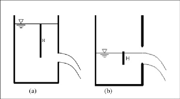
A partially submerged orifice is defined as an opening in a barrier or wall where the water level on the downstream side is above the bottom edge of the orifice but below the top edge. This creates a situation where part of the orifice is submerged under water while the remaining portion is exposed to atmospheric pressure.
This configuration is distinct from a fully submerged orifice, where both upstream and downstream water levels are above the top of the orifice, and a free orifice, where the downstream side is open to the atmosphere and the water level is below the bottom edge of the orifice.
In practical applications, partially submerged orifices can occur in:
- Dam spillways during partial opening
- Control gates in irrigation canals
- Industrial tanks with adjustable outlet levels
- Water treatment facilities with variable flow control
Understanding the discharge characteristics of partially submerged orifices is essential for proper system design and operation, as incorrect calculations can lead to inadequate flow control or system overflows.
Concept of Divided Flow
The key to analyzing flow through a partially submerged orifice lies in recognizing that the orifice can be conceptually divided into two separate sections, each with distinct flow characteristics. This approach simplifies the analysis by allowing us to treat each section according to its specific flow conditions.
Lower Submerged Portion
The lower portion of the orifice, which is below the downstream water level, operates as a submerged orifice. In this section, the flow is driven by the difference in water levels between the upstream and downstream sides. The discharge through this portion can be calculated using the standard submerged orifice formula.
Key characteristics of the submerged portion include:
- Flow is driven by the head difference between upstream and downstream water levels
- Pressure at the downstream side affects the flow rate
- No free surface effects at the discharge point
Upper Free-Discharging Portion
The upper portion of the orifice, which is above the downstream water level, functions as a free-discharging orifice. The flow in this section is driven by the head of water above the center of the orifice opening. This portion behaves similarly to a standard orifice with free discharge to the atmosphere.
Key characteristics of the free-discharging portion include:
- Flow is driven by the head of water above the orifice
- Discharge occurs into atmospheric pressure
- Free surface effects are present at the discharge point
By treating these two portions separately and then summing their individual discharges, we can accurately determine the total flow through the partially submerged orifice.
Derivation of Discharge Formula
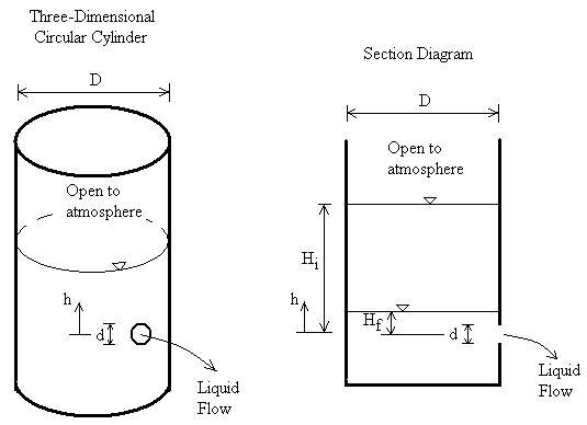
To derive the formula for discharge through a partially submerged orifice, we need to calculate the discharge for each portion separately and then combine them to get the total discharge. Let’s consider a rectangular orifice with height H, width B, and with the downstream water level at a height h above the bottom of the orifice.
Discharge Calculation for the Submerged Portion (Q₁)
For the submerged portion of height h, we calculate the discharge Q₁ using the submerged orifice formula:
Where:
- C_d is the coefficient of discharge
- A₁ is the area of the submerged portion = B × h
- g is the acceleration due to gravity
- H₁ is the effective head for the submerged portion
The effective head H₁ is the difference between the upstream water level and the downstream water level. If we denote the upstream water level above the bottom of the orifice as H_total, then:
Therefore:
Discharge Calculation for the Free-Discharging Portion (Q₂)
For the free-discharging portion, which has a height of (H – h), we need to integrate over the area since the head varies from h to H_total. We consider a small horizontal strip of height dh at a depth h’ below the upstream water level.
The discharge through this small strip is:
To find the total discharge Q₂, we integrate from h’ = h to h’ = H_total:
Solving the integral:
Total Discharge (Q_total)
The total discharge through the partially submerged orifice is the sum of the discharges through the submerged and free-discharging portions:
This can be simplified to:
This formula provides a comprehensive method for calculating the total discharge through a partially submerged orifice, taking into account both the submerged and free-discharging portions.
Factors Affecting Discharge Through Partially Submerged Orifices
Several factors influence the discharge through partially submerged orifices, and understanding these factors is crucial for accurate calculations and proper system design.
Coefficient of Discharge (C_d)
The coefficient of discharge accounts for losses in the system and typically ranges from 0.6 to 0.9 for well-designed orifices. Factors affecting C_d include:
- Shape and sharpness of the orifice edges
- Reynolds number of the flow
- Approach velocity of the fluid
- Degree of submergence
Orifice Dimensions
The dimensions of the orifice directly affect the discharge capacity. Larger orifices allow more flow, but the relationship is not linear due to the complex interaction between the two flow regimes.
Head Conditions
The upstream and downstream head conditions determine the effective heads for both the submerged and free-discharging portions. Changes in these heads will affect the discharge through both portions differently, leading to complex variations in total discharge.
Orifice Shape
While we’ve focused on rectangular orifices, partially submerged orifices can have various shapes, including circular, triangular, or trapezoidal. The shape affects the distribution of flow between the two portions and requires modifications to the calculation approach.
Sample Problem
Let’s work through a practical example to illustrate the application of these principles. Consider a rectangular orifice in a dam spillway with the following characteristics:
- Width (B) = 3 meters
- Height (H) = 2 meters
- Upstream water level above the bottom of the orifice (H_total) = 1.8 meters
- Downstream water level above the bottom of the orifice (h) = 0.7 meters
- Coefficient of discharge (C_d) = 0.65
- Acceleration due to gravity (g) = 9.81 m/s²
First, let’s identify the two portions:
- Submerged portion height = 0.7 meters
- Free-discharging portion height = 1.8 – 0.7 = 1.1 meters
Calculating Q₁ (Submerged Portion)
Using the formula for submerged orifice:
Substituting values:
Calculating Q₂ (Free-Discharging Portion)
Using the formula for free-discharging portion:
First, calculate the required terms:
Now substituting all values:
Total Discharge
The total discharge through the partially submerged orifice is:
This example demonstrates how the total discharge is the sum of the flows through the two distinct portions of the orifice. The free-discharging portion contributes significantly more to the total discharge in this case, which is typical when the upstream head is relatively high compared to the downstream water level.
Engineering Applications
The principles of flow through partially submerged orifices have numerous applications in engineering practice:
Dam and Spillway Design
In dam design, spillways often operate with partially submerged conditions, especially during moderate flood events. Engineers use these calculations to determine the discharge capacity of spillways under various operating conditions to ensure the dam can safely pass flood flows.
Irrigation Systems
In irrigation canals, control gates and orifices are used to regulate flow rates. During varying flow conditions, these structures may operate in partially submerged conditions, requiring accurate discharge calculations for proper water distribution.
Water Treatment Plants
In water treatment facilities, weirs and orifices are used for flow measurement and control. Understanding the behavior of partially submerged orifices helps in designing accurate flow measurement systems and in optimizing treatment processes.
Industrial Processes
Many industrial processes involve the controlled discharge of liquids from tanks and vessels. When the discharge point is partially submerged in a receiving tank, the principles discussed here are essential for proper system design.
Comparison with Other Orifice Types
It’s instructive to compare the discharge through partially submerged orifices with other orifice configurations to understand the relative flow characteristics:
| Orifice Type | Flow Characteristics | Discharge Formula | Typical Applications |
|---|---|---|---|
| Fully Submerged | Driven by head difference | Q = C_d × A × √(2gH) | Underwater discharge, sluice gates |
| Partially Submerged | Combined submerged and free flow | Q = Q₁ + Q₂ (as derived) | Dam spillways, variable head conditions |
| Free Discharge | Driven by upstream head | Q = C_d × A × √(2gH) | Atmospheric discharge, overflow weirs |
This comparison highlights how partially submerged orifices represent an intermediate case between fully submerged and free discharge orifices, combining aspects of both flow regimes.
Advanced Considerations
For more precise calculations and special applications, engineers may need to consider additional factors:
Velocity of Approach
When the upstream tank or channel is relatively small, the velocity of approach can significantly affect the discharge. This velocity reduces the effective head available for discharge and should be accounted for in precise calculations.
Unsteady Flow Effects
In situations where the upstream or downstream water levels are changing rapidly, unsteady flow effects become important. These effects can cause the actual discharge to differ from steady-state calculations.
Turbulence and Viscous Effects
For highly viscous fluids or at very low Reynolds numbers, the flow may become laminar, which significantly changes the relationship between head and discharge. In turbulent flows, the coefficient of discharge may vary with Reynolds number.
Scale Effects
Model studies and scale models may not perfectly represent prototype behavior due to differences in Reynolds number and other dimensionless parameters. Scale effects should be considered when extrapolating model results to full-scale applications.
Measurement and Control
Accurate measurement and control of flow through partially submerged orifices is important for many applications:
Flow Measurement
Partially submerged orifices can be used as flow measurement devices, but they require careful calibration due to the complex flow patterns. Modern measurement techniques, including ultrasonic and electromagnetic flow meters, are often preferred for more accurate measurements.
Flow Control
In control applications, partially submerged orifices can provide variable discharge characteristics as the downstream level changes. This can be advantageous in some applications but may require careful design to achieve desired control characteristics.
Conclusion
The analysis of discharge through partially submerged orifices represents an important and practical aspect of hydraulic engineering. By recognizing that such orifices can be conceptually divided into submerged and free-discharging portions, engineers can accurately calculate the total discharge using established principles.
The derived formula for total discharge, which is the sum of the discharges through the two portions, provides a comprehensive method for handling this complex flow situation. The sample problem demonstrates the practical application of these principles and shows how the two portions contribute differently to the total discharge.
Applications of this knowledge span numerous engineering disciplines, from civil engineering projects like dam design to industrial processes involving fluid control. Understanding the factors that affect discharge through partially submerged orifices enables engineers to design more efficient and reliable hydraulic systems.
While the basic analysis provides good approximations for many applications, engineers must be aware of advanced considerations such as velocity of approach, unsteady flow effects, and scale effects when dealing with critical or precision applications.
As with all hydraulic calculations, proper validation through experimentation and the application of appropriate safety factors are important for ensuring reliable designs. The principles discussed here form a solid foundation for understanding and analyzing flow through partially submerged orifices in various engineering contexts.
Future developments in computational fluid dynamics and advanced measurement techniques continue to enhance our understanding of these complex flow phenomena, enabling even more accurate predictions and better system designs.