In the realm of mechanical engineering and power transmission, helical gears stand as one of the most versatile and widely utilized gear types for applications requiring smooth, quiet, and efficient power transfer between parallel shafts. The distinctive angled tooth design of helical gears provides numerous operational advantages that have made them indispensable in modern machinery, from automotive transmissions to industrial equipment and aerospace applications.
Understanding the comprehensive advantages, disadvantages, and applications of helical gears is essential for engineers, designers, and maintenance professionals who work with mechanical power transmission systems. This knowledge enables informed decision-making regarding gear selection, system optimization, and maintenance planning.
Introduction to Helical Gears
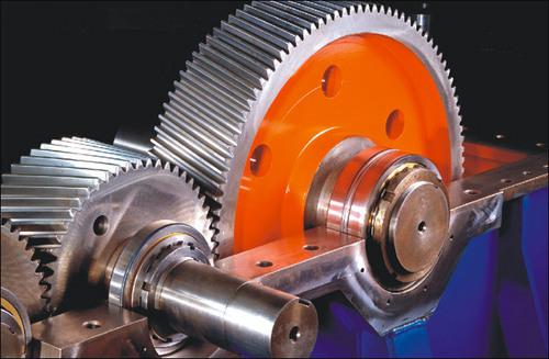
Helical gears are cylindrical gears with teeth that are cut at an angle (known as the helix angle) to the gear axis, creating a helical pattern around the gear circumference. This helix angle, typically ranging from 15° to 30°, fundamentally changes the engagement characteristics compared to straight-toothed spur gears, resulting in distinct operational properties that define the advantages and disadvantages of helical gears.
The angled tooth design creates a progressive engagement pattern where teeth gradually come into contact along their length, rather than engaging abruptly across the full tooth width as in spur gears. This fundamental difference in engagement mechanics is the source of many of the unique characteristics that distinguish helical gears from other gear types.
The helical gear configuration can be manufactured with either a right-hand or left-hand helix, and in gear pairs, mating gears must have opposite hand configurations to ensure proper meshing. This requirement adds a layer of complexity to helical gear design and manufacturing but is essential for achieving the desired operational characteristics.
Advantages of Helical Gears
Helical gears offer numerous operational advantages that make them the preferred choice for many power transmission applications where smooth operation, noise reduction, and high load capacity are priorities.
Smooth and Quiet Operation
Perhaps the most immediately noticeable advantage of helical gears is their exceptionally smooth and quiet operation compared to straight-toothed gears. This characteristic stems directly from the progressive engagement pattern created by the helical tooth design.
In helical gears, the engagement begins at one end of the tooth and progresses gradually across the tooth face, creating a smooth transition of load transfer rather than the abrupt engagement characteristic of spur gears. This progressive engagement significantly reduces:
- Impact Loading: The gradual engagement eliminates the sudden impact forces that generate noise and vibration in spur gears
- Acoustic Emission: The smooth load transfer produces significantly lower noise levels across the operating spectrum
- Vibration Reduction: Reduced impact loading translates to lower vibration amplitudes and frequencies
- System Stability: Smooth engagement contributes to overall system stability and reduced wear on supporting components
This quiet operation makes helical gears particularly valuable in applications where noise control is critical, such as automotive transmissions, consumer appliances, and precision instruments.
Higher Load Capacity
Helical gears typically exhibit higher load capacity compared to spur gears of equivalent size, primarily due to the increased contact ratio and more favorable load distribution characteristics.
The helical tooth design results in:
- Increased Contact Ratio: More than one pair of teeth is typically in contact simultaneously, distributing loads over multiple contact points
- Longer Contact Line: The effective contact length is increased due to the helix angle, spreading loads over a larger area
- Even Load Distribution: Progressive engagement reduces peak loading on individual tooth contacts
- Reduced Stress Concentrations: Distributed loading minimizes localized stress peaks that can lead to failure
These factors combine to enable helical gears to handle higher torque loads for a given size compared to spur gears, making them valuable in high-power transmission applications.
Better Shock Absorption
The progressive engagement characteristic of helical gears provides superior shock absorption capabilities compared to spur gears, making them particularly suitable for applications subject to variable or冲击loading conditions.
The shock absorption benefits include:
- Gradual Load Application: Progressive tooth engagement spreads冲击loads over time rather than applying them instantaneously
- Damping Characteristics: The engagement pattern provides inherent damping that reduces the transmission of冲击forces
- Reduced Fatigue Loading: Smoother load application reduces cyclic stress variations that contribute to fatigue failure
- Extended Component Life: Reduced冲击loading contributes to longer service life for gears and supporting components
Higher Speed Capability
Helical gears are inherently better suited for high-speed applications due to their smooth engagement characteristics and reduced noise and vibration generation.
The high-speed capabilities include:
- Reduced Dynamic Effects: Smooth engagement minimizes dynamic forces that become problematic at high speeds
- Lower Noise Generation: Critical for high-speed applications where aerodynamic and mechanical noise must be controlled
- Improved Stability: Reduced vibration at high speeds contributes to system stability and reliability
- Extended Operating Range: Ability to operate effectively at speeds where spur gears would generate excessive noise and vibration
Improved Efficiency at Higher Loads
While helical gears have slightly lower efficiency than spur gears under light loads due to sliding contact, they can actually demonstrate improved efficiency under heavy load conditions due to better load distribution and reduced localized losses.
The efficiency advantages include:
- Reduced Localized Heating: Even load distribution minimizes hot spots that can reduce efficiency
- Lower Wear Rates: Distributed loading reduces wear that can increase friction losses over time
- Better Lubrication: Improved contact patterns can enhance lubricant film formation and retention
Disadvantages of Helical Gears
Despite their numerous advantages, helical gears also present several disadvantages that must be carefully considered during design, selection, and application planning.
Axial Thrust Forces
The most significant disadvantage of helical gears is the generation of axial thrust forces due to the helix angle, which creates a force component parallel to the gear axis that must be managed through appropriate bearing design.
The axial thrust implications include:
- Thrust Bearing Requirements: Additional thrust bearings are required to accommodate axial forces, increasing complexity and cost
- Bearing Load Increase: Axial forces add to the total bearing load, potentially requiring larger or more robust bearings
- System Design Complexity: Additional considerations for thrust force management complicate system design
- Maintenance Requirements: Thrust bearings require specific maintenance attention and monitoring
The axial thrust force can be calculated as:
Where β is the helix angle. This relationship shows that axial thrust increases with helix angle, creating a design trade-off between load capacity benefits and thrust force penalties.
Higher Manufacturing Costs
Helical gears typically incur higher manufacturing costs compared to spur gears due to the complexity of their geometry and the specialized tooling and processes required for production.
The cost factors include:
- Specialized Tooling: Helical cutting tools and angle-capable machinery are more expensive than straight-cutting equipment
- Complex Manufacturing Processes: Helical hobbing and grinding require more sophisticated equipment and skilled operators
- Extended Production Times: More complex geometry typically requires longer machining times
- Quality Control Complexity: Additional measurements and inspections are required for helix angle accuracy
Slightly Lower Efficiency
Helical gears typically exhibit slightly lower efficiency compared to spur gears, primarily due to the sliding contact between mating teeth that occurs as a result of the helix angle.
The efficiency considerations include:
- Sliding Friction Losses: Axial component of tooth contact creates sliding friction that reduces efficiency
- Lubrication Requirements: Increased sliding contact may require specialized lubricants or more frequent lubrication
- Temperature Effects: Sliding friction can generate additional heat that affects efficiency and component life
Typical efficiency values are:
- Spur Gears: 98-99% efficiency
- Helical Gears: 97-98% efficiency
While the efficiency difference appears small, it can be significant in high-power applications where even small losses translate to substantial energy consumption and heat generation.
Increased Design Complexity
The design of helical gear systems is inherently more complex than spur gear systems due to the additional geometric and operational considerations introduced by the helix angle.
The complexity factors include:
- Helix Angle Optimization: Selection of optimal helix angle requires balancing multiple performance factors
- Hand Selection: Proper selection of right-hand and left-hand configurations for mating gears
- Thrust Force Calculations: Additional analytical requirements for axial force determination and management
- Alignment Sensitivity: Helical gears are more sensitive to misalignment than spur gears
Sensitivity to Misalignment
Helical gears are more sensitive to shaft misalignment compared to spur gears, which can lead to uneven load distribution and premature failure if not properly addressed.
The misalignment sensitivity includes:
- Uneven Load Distribution: Misalignment can cause load concentration on one side of the gear face
- Premature Wear: Uneven loading accelerates wear in high-load areas
- Noise Generation: Misalignment can negate the noise benefits of helical gears
- Reduced Life: Poor alignment significantly reduces gear and bearing service life
Applications of Helical Gears
The unique combination of advantages offered by helical gears makes them suitable for a wide range of applications across numerous industries where their benefits outweigh their disadvantages.
Automotive Industry
The automotive industry represents one of the largest applications for helical gears, particularly in transmissions and differentials where smooth operation and noise reduction are critical.
Key automotive applications include:
- Manual Transmissions: Gear sets in constant mesh manual transmissions for smooth shifting and quiet operation
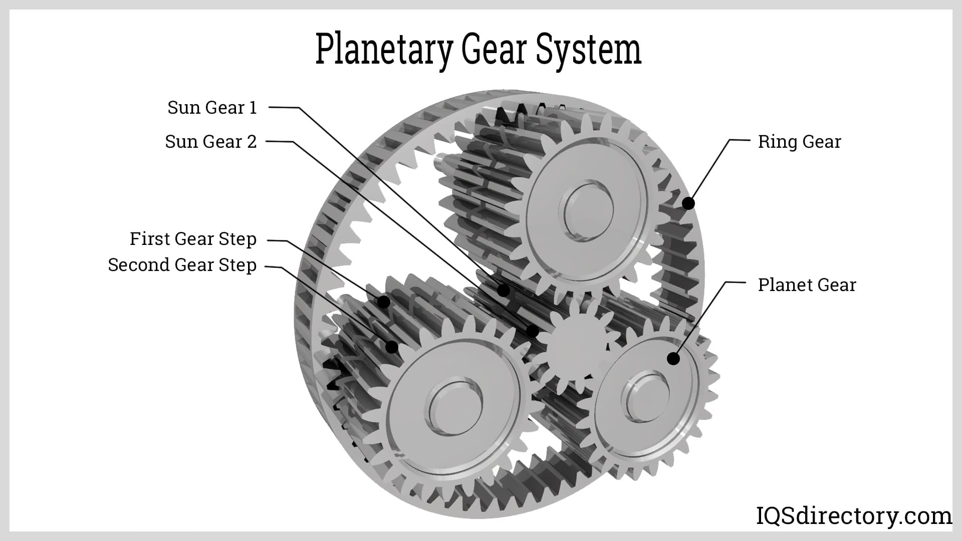
- Automatic Transmissions: Planetary gear sets and reduction gears in automatic transmissions
- Differentials: Ring and pinion gears in rear axles for power distribution to wheels
- Engine Components: Timing gears, oil pumps, and accessory drives requiring quiet operation
- Steering Systems: Rack and pinion steering mechanisms for smooth, precise control
Aerospace Industry
Aerospace applications demand the high reliability, smooth operation, and precise power transmission capabilities that helical gears provide.
Aerospace applications include:
- Aircraft Engines: Reduction gears in turboprop engines and accessory gearboxes
- Helicopter Transmissions: Main rotor gearboxes and tail rotor drives
- Flight Controls: Actuator drives for precise control surface positioning
- Landing Gear Systems: Retraction mechanisms and door actuators
- Environmental Systems: Air conditioning and pressurization system drives
Industrial Machinery
Industrial applications benefit from the high load capacity and smooth operation characteristics of helical gears in demanding operating environments.
Industrial applications include:
- Machine Tools: Spindle drives, feed mechanisms, and precision positioning systems
- Conveyor Systems: Drive units for heavy-duty conveyor applications
- Manufacturing Equipment: Presses, extruders, and processing machinery requiring high torque transmission
- Power Generation: Turbine drives, generator couplings, and auxiliary power transmission
- Material Handling: Crane and hoist mechanisms requiring smooth, controlled operation
Consumer Products
Consumer applications leverage the quiet operation and smooth performance of helical gears to enhance user experience and product reliability.
Consumer applications include:
- Home Appliances: Washing machines, dryers, dishwashers, and kitchen appliances
- Power Tools: Drills, saws, and sanders requiring smooth power transmission
- Automotive Accessories: Window regulators, seat adjusters, and sunroof mechanisms
- Office Equipment: Printers, copiers, and fax machines requiring quiet operation
- Recreational Equipment: Exercise equipment, marine propulsion systems, and outdoor power equipment
Design Considerations
Successful application of helical gears requires careful attention to numerous design factors that influence performance, reliability, and cost-effectiveness.
Helix Angle Selection
The helix angle is a critical design parameter that significantly affects helical gear performance and must be optimized for specific applications.
Key considerations for helix angle selection include:
- Load Capacity: Increasing helix angle generally increases load capacity due to longer contact lines
- Axial Thrust: Axial thrust force increases with helix angle, requiring larger thrust bearings
- Efficiency: Efficiency typically decreases slightly with increasing helix angle due to increased sliding
- Manufacturing Costs: Larger helix angles may require more complex manufacturing processes
- Application Requirements: Specific operational requirements may dictate optimal helix angle ranges
Typical helix angle ranges:
- Light Load Applications: 15-20° helix angle
- Moderate Load Applications: 20-25° helix angle
- Heavy Load Applications: 25-30° helix angle
Material Selection
Material selection for helical gears must consider the specific loading conditions, operating environment, and performance requirements of the application.
Common material considerations include:
- Strength Requirements: Material must withstand contact and bending stresses under maximum loading conditions
- Hardness Characteristics: Surface hardness for wear resistance and core toughness for fatigue resistance
- Corrosion Resistance: Environmental resistance for specific operating conditions
- Manufacturability: Material workability for required manufacturing processes
- Cost Considerations: Balance between material costs and performance benefits
Lubrication Requirements
Proper lubrication is essential for helical gear performance and longevity, particularly due to the sliding contact between mating teeth.
Lubrication considerations include:
- Viscosity Selection: Lubricant viscosity must balance film formation with operating temperature requirements
- Additive Packages: Anti-wear and extreme pressure additives for high-load applications
- Delivery Methods: Splash lubrication, pressure lubrication, or grease lubrication based on application needs
- Contamination Control: Filtration and sealing to prevent abrasive contamination
- Maintenance Schedules: Regular lubricant analysis and replacement intervals
Maintenance and Troubleshooting
Proper maintenance of helical gears is essential for achieving optimal performance and service life, with specific considerations for the unique characteristics of helical gear systems.
Routine Maintenance
Regular maintenance activities help ensure reliable helical gear operation and early detection of potential issues.
Key maintenance activities include:
- Lubrication Monitoring: Regular inspection and analysis of lubricant condition and contamination levels
- Vibration Analysis: Monitoring vibration patterns for early detection of misalignment or wear
- Temperature Monitoring: Tracking operating temperatures for signs of excessive friction or inadequate lubrication
- Visual Inspection: Checking for signs of wear, damage, or contamination on gear teeth and surfaces
- Bearing Condition: Special attention to thrust bearing condition due to axial loading
Common Failure Modes
Understanding common failure modes helps in developing effective maintenance strategies and troubleshooting procedures.
Typical helical gear failure modes include:
- Pitting: Surface fatigue failure resulting in small craters on gear teeth
- Scoring: Adhesive wear caused by inadequate lubrication or excessive sliding
- Cracking: Fatigue cracking initiated by cyclic loading or material defects
- Wear: Progressive removal of material from tooth surfaces due to abrasion or adhesion
- Plastic Deformation: Permanent deformation of gear teeth under excessive loads
Troubleshooting Approaches
Systematic troubleshooting approaches help identify and resolve helical gear issues efficiently.
Effective troubleshooting includes:
- Condition Monitoring: Regular data collection on vibration, temperature, and lubricant condition
- Diagnostic Analysis: Correlating symptoms with potential causes using analytical techniques
- Corrective Actions: Implementing appropriate solutions based on root cause analysis
- Preventive Measures: Developing strategies to prevent recurrence of identified issues
Manufacturing and Quality Control
The manufacturing process and quality control procedures for helical gears are more complex than for spur gears due to their geometric complexity and performance requirements.
Manufacturing Processes
Helical gear manufacturing requires specialized processes and equipment to achieve the required accuracy and surface finish.
Key manufacturing processes include:
- Helical Hobbing: Primary manufacturing method using helical cutting tools with precise angle control
- Generating Grinding: Precision finishing process for high-accuracy applications
- Form Milling: Specialized milling for large or unusual helical gear configurations
- Quality Inspection: Comprehensive measurement and verification of all critical dimensions
Quality Control Standards
Stringent quality control standards ensure helical gears meet performance and reliability requirements.
Quality control requirements include:
- Dimensional Accuracy: Precise measurement of tooth profile, helix angle, and spacing
- Surface Finish: Controlled surface roughness to optimize lubrication and reduce wear
- Material Properties: Verification of hardness, strength, and metallurgical characteristics
- Functional Testing: Performance verification under simulated operating conditions
Comparison with Other Gear Types
Understanding how helical gears compare with other gear types helps in making informed selection decisions for specific applications.
| Characteristic | Helical Gears | Spur Gears | Bevel Gears | Worm Gears |
|---|---|---|---|---|
| Noise Level | Low | High | Moderate | Very Low |
| Load Capacity | High | Moderate | Moderate | High |
| Efficiency | 97-98% | 98-99% | 95-98% | 40-90% |
| Speed Capability | High | Moderate | Moderate | Low |
| Manufacturing Cost | Moderate | Low | High | Moderate |
| Axial Thrust | Present | None | Minimal | Present |
| Shaft Alignment | Critical | Important | Critical | Important |
Sample Problems and Calculations
Working through sample problems helps illustrate the practical application of helical gear principles and calculations.
Problem 1: Axial Thrust Calculation
A helical gear pair transmits 30 kW of power at 1,200 rpm. The pinion has 20 teeth, the gear has 60 teeth, the normal module is 4 mm, and the helix angle is 25°. Calculate the axial thrust force on each gear.
Given:
- Power = 30 kW
- Pinion Speed = 1,200 rpm
- Pinion Teeth (Z₁) = 20
- Gear Teeth (Z₂) = 60
- Normal Module (mₙ) = 4 mm
- Helix Angle (β) = 25°
Solution:
First, calculate the pitch diameters:
Calculate the torque on the pinion:
Calculate the tangential force:
Calculate the axial thrust force:
The axial thrust force on the pinion is 2,520 N. An equal and opposite thrust force acts on the gear, which must be accommodated by appropriate thrust bearings.
Problem 2: Efficiency Comparison
Compare the power loss due to friction in a helical gear pair versus a spur gear pair transmitting 50 kW at 98% efficiency. Assume the helical gear efficiency is 97%.
Given:
- Input Power = 50 kW
- Spur Gear Efficiency = 98%
- Helical Gear Efficiency = 97%
Solution:
For Spur Gears:
For Helical Gears:
The helical gear system loses 0.5 kW more power than the spur gear system. In annual operation (8,760 hours), this difference amounts to:
At an electricity cost of $0.10/kWh, this represents an additional annual operating cost of $438 for the helical gear system. This cost must be weighed against the benefits of helical gears when making selection decisions.
Problem 3: Contact Ratio Analysis
Calculate and compare the contact ratios for a spur gear pair and a helical gear pair with the following specifications:
- Module = 3 mm
- Pressure Angle = 20°
- Face Width = 30 mm
- Helix Angle = 25° (for helical gears)
Solution:
For Spur Gears (εα):
For Helical Gears (εγ):
The helical gear pair has a contact ratio more than double that of the spur gear pair (2.44 vs. 1.09). This higher contact ratio contributes to the improved load distribution and smoother operation characteristic of helical gears.
Conclusion
Helical gears represent a sophisticated and versatile solution for power transmission applications where smooth operation, reduced noise, and high load capacity are prioritized. Their angled tooth design fundamentally transforms the engagement characteristics compared to straight-toothed spur gears, creating a unique combination of advantages that have made them indispensable in modern mechanical systems.
The comprehensive advantages of helical gears, including smooth and quiet operation, higher load capacity, superior shock absorption, enhanced high-speed capability, and improved efficiency under heavy loads, make them the preferred choice for numerous critical applications. These benefits are particularly valuable in automotive transmissions, aerospace systems, precision machinery, and consumer products where user experience and system reliability are paramount.
However, these advantages come with corresponding disadvantages that must be carefully considered in design and application planning. The generation of axial thrust forces requires additional thrust bearings and complicates system design. Higher manufacturing costs, slightly reduced efficiency, increased design complexity, and sensitivity to misalignment present challenges that may make helical gears less suitable for cost-sensitive or simplicity-driven applications.
The widespread applications of helical gears across automotive, aerospace, industrial, and consumer sectors demonstrate their value and versatility. Their ability to meet the demanding requirements of these diverse applications while providing reliable, efficient power transmission has established helical gears as a cornerstone of modern mechanical engineering.
Design considerations for helical gears emphasize the importance of helix angle optimization, material selection, and lubrication management. These factors significantly influence performance, reliability, and service life, requiring careful attention during the design process. The sample problems demonstrate the quantitative aspects of helical gear analysis, including axial thrust calculations, efficiency comparisons, and contact ratio analysis that guide practical engineering decisions.
Maintenance and troubleshooting considerations highlight the need for specialized attention to thrust bearing condition, lubrication management, and misalignment sensitivity. Regular monitoring and preventive maintenance are essential for achieving optimal helical gear performance and longevity.
Manufacturing and quality control requirements for helical gears are more complex than for spur gears, necessitating specialized equipment, processes, and inspection procedures. These requirements contribute to higher manufacturing costs but are essential for achieving the precision and performance characteristics that define quality helical gears.
The comparison with other gear types illustrates the unique position of helical gears in the spectrum of power transmission solutions. They offer an optimal balance of performance characteristics for parallel shaft applications, combining the efficiency of spur gears with the smooth operation of worm gears while avoiding the complexity of bevel gears for most applications.
The sample calculations demonstrate the practical implications of helical gear characteristics, showing how axial thrust forces, efficiency differences, and contact ratios translate into real-world engineering considerations. These quantitative relationships provide the foundation for informed decision-making in gear selection and system design.
For students and practitioners of mechanical engineering and maintenance, understanding the comprehensive advantages, disadvantages, and applications of helical gears provides essential knowledge for successful system design, operation, and maintenance. This understanding enables engineers to make informed decisions that balance performance requirements with cost and complexity considerations.
As technology continues to advance, helical gears are benefiting from improvements in materials science, manufacturing precision, and design optimization techniques. These developments are enhancing the already impressive capabilities of helical gears while potentially reducing some of their traditional disadvantages.
Looking forward, emerging technologies such as additive manufacturing, advanced materials, and computational analysis promise to further expand the capabilities and applications of helical gears. These developments may enable new design possibilities and performance levels that could redefine the role of helical gears in mechanical systems.
In conclusion, helical gears represent a mature yet evolving technology that continues to provide exceptional value in power transmission applications. Their unique combination of characteristics makes them irreplaceable in many critical applications, and their continued development promises even greater capabilities for future engineering challenges. Understanding these systems is essential for any professional working in mechanical design, power transmission, or maintenance of rotating machinery.