In the field of mechanical engineering and maintenance, gear systems are fundamental components for power transmission in countless machines and mechanisms. Among the various types of gears used in industrial applications, helical gears and spur gears represent two of the most common and important configurations for transmitting power between parallel shafts.
Understanding the differences between helical gears and spur gears is essential for engineers, designers, and maintenance professionals who work with mechanical power transmission systems. Each gear type offers distinct advantages and disadvantages that make them suitable for specific applications, and the proper selection between these two options can significantly impact system performance, efficiency, noise levels, and service life.
Introduction to Gear Types
Gears are mechanical components with teeth that mesh with corresponding teeth on another gear to transmit motion and power between rotating shafts. The selection of gear type depends on various factors including load requirements, speed considerations, noise constraints, efficiency targets, and manufacturing costs.
Both helical gears and spur gears belong to the family of cylindrical gears, which are designed for power transmission between parallel shafts. Despite this common classification, these two gear types differ significantly in their tooth geometry, performance characteristics, and application suitability.
The fundamental differences between these gear types stem from their tooth orientation and the resulting contact patterns during meshing. These differences create distinct operational characteristics that make each type suitable for specific applications and operating conditions.
Spur Gears
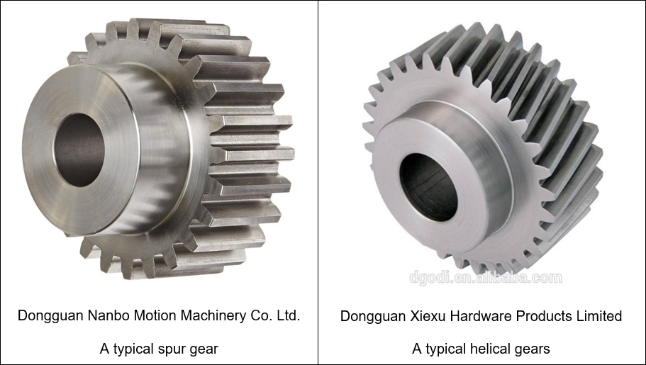
Spur gears represent the most basic and widely used type of cylindrical gear. They are characterized by straight teeth that are parallel to the gear axis, creating a simple yet effective means of power transmission between parallel shafts.
Definition and Characteristics
Spur gears are cylindrical gears with straight teeth that project radially from the gear surface and are parallel to the gear axis. This simple geometry makes them relatively easy to manufacture and maintain, contributing to their widespread use in various mechanical applications.
Key characteristics of spur gears include:
- Straight Teeth: Teeth are straight and parallel to the gear axis
- Simple Geometry: Straightforward design facilitates manufacturing and inspection
- Radial Load: Transmit forces radially, creating no axial thrust
- Simultaneous Meshing: Entire tooth width engages simultaneously during meshing
- High Efficiency: Minimal sliding contact results in high power transmission efficiency
Advantages of Spur Gears
Spur gears offer several advantages that make them suitable for many applications:
- Simplicity: Simple design and manufacturing process reduce complexity and potential failure modes
- Cost-Effectiveness: Lower manufacturing costs compared to more complex gear types
- High Efficiency: Typically achieve efficiencies of 98-99% due to minimal sliding contact
- Load Capacity: Can handle high loads due to full tooth engagement
- No Axial Thrust: Radial force transmission eliminates axial bearing loads
- Predictable Performance: Well-established design principles and performance characteristics
Disadvantages of Spur Gears
Despite their advantages, spur gears also have notable disadvantages:
- Noise Generation: Characteristic clicking or clattering noise at high speeds due to abrupt tooth engagement
- Vibration: Impact loading creates vibration that can affect system stability
- Speed Limitations: Not suitable for very high-speed applications due to noise and vibration issues
- Load Concentration: Sudden load application can create stress concentrations
- Wear Patterns: May exhibit uneven wear due to impact loading
Helical Gears
Helical gears represent an advancement over spur gears, featuring teeth that are cut at an angle (helix angle) to the gear axis. This angled tooth design creates several distinct operational characteristics that differentiate helical gears from their spur gear counterparts.
Definition and Characteristics
Helical gears are cylindrical gears with teeth that are cut at an angle to the gear axis, creating a helical pattern around the gear circumference. This helix angle typically ranges from 15° to 30°, with 20° being a common standard value.
Key characteristics of helical gears include:
- Angled Teeth: Teeth are cut at a helix angle to the gear axis
- Gradual Engagement: Teeth engage progressively along their length rather than simultaneously
- Axial Thrust: Helix angle creates axial force component that must be managed
- Multiple Tooth Contact: More than one tooth pair is typically in contact during meshing
- Smoothing Action: Helical tooth engagement reduces impact loading and noise
Advantages of Helical Gears
Helical gears provide several advantages over spur gears:
- Quiet Operation: Gradual tooth engagement significantly reduces noise compared to spur gears
- Smooth Motion: Progressive engagement reduces vibration and冲击loading
- Higher Load Capacity: Multiple simultaneous tooth contacts distribute loads more evenly
- Higher Speed Capability: Better suited for high-speed applications due to reduced noise and vibration
- Improved Durability: Even load distribution extends gear life
- Better Shock Absorption: Helical engagement dampens shock loads more effectively
Disadvantages of Helical Gears
Helical gears also have notable disadvantages that must be considered:
- Axial Thrust: Helix angle creates axial force that requires thrust bearings
- Higher Manufacturing Cost: More complex geometry increases production costs
- Slightly Lower Efficiency: Sliding contact between teeth reduces efficiency compared to spur gears
- Increased Complexity: More complex design and assembly requirements
- Thrust Bearing Requirements: Additional bearings needed to manage axial forces
Detailed Comparison
A comprehensive comparison of helical gears and spur gears reveals the fundamental differences that drive their respective applications and performance characteristics.
| Characteristic | Spur Gears | Helical Gears |
|---|---|---|
| Tooth Orientation | Straight, parallel to gear axis | Angled (helical) to gear axis |
| Engagement Pattern | Simultaneous full-width engagement | Progressive line contact |
| Noise Level | High (clicking/clattering) | Low (smooth, quiet) |
| Vibration | High (impact loading) | Low (gradual loading) |
| Axial Forces | None (pure radial loading) | Present (requires thrust bearings) |
| Load Distribution | Single tooth contact at a time | Multiple teeth in contact simultaneously |
| Efficiency | Very High (98-99%) | High (97-98%) |
| Speed Capability | Moderate (limited by noise/vibration) | High (suitable for high-speed operation) |
| Manufacturing Complexity | Simple (straight tooth cutting) | Complex (angled tooth cutting) |
| Cost | Low (simple design and manufacturing) | Moderate to High (complex geometry) |
| Maintenance Requirements | Low (simple design) | Moderate (thrust bearing maintenance) |
Noise and Vibration Characteristics
The noise and vibration characteristics of these two gear types differ significantly due to their engagement patterns:
- Spur Gears: Generate characteristic clicking or clattering noise due to abrupt tooth engagement across the full tooth width
- Helical Gears: Operate more quietly due to progressive tooth engagement that distributes the loading over time
This difference is particularly important in applications where noise control is critical, such as in automotive transmissions, consumer appliances, and precision instruments.
Load Capacity and Distribution
The load handling characteristics also differ significantly:
- Spur Gears: Handle loads effectively but with concentration at the point of engagement
- Helical Gears: Distribute loads over multiple teeth simultaneously, reducing peak stresses
This load distribution advantage makes helical gears particularly suitable for high-torque applications where durability is critical.
Efficiency Considerations
Efficiency differences arise from the contact mechanics of the two gear types:
- Spur Gears: Achieve very high efficiencies (98-99%) due to primarily rolling contact with minimal sliding
- Helical Gears: Slightly lower efficiencies (97-98%) due to sliding contact between angled teeth
While the efficiency difference is relatively small, it can be significant in high-power applications where even small losses translate to substantial energy consumption.
Applications
The distinct characteristics of helical and spur gears make them suitable for different applications based on specific operational requirements.
Applications for Spur Gears
Spur gears find applications in situations where their characteristics are advantageous:
- Low-Speed Applications: Simple machinery operating at moderate speeds where noise is not critical
- Cost-Sensitive Designs: Applications where minimizing manufacturing costs is important
- High-Efficiency Requirements: Systems where maximum power transmission efficiency is critical
- Simple Maintenance: Equipment requiring straightforward maintenance procedures
- Axial Load Constraints: Applications where axial forces must be avoided
Examples include simple industrial machinery, hand tools, basic conveyor systems, and low-speed power transmission applications.
Applications for Helical Gears
Helical gears excel in applications that benefit from their unique characteristics:
- High-Speed Operations: Automotive transmissions, aircraft engines, and high-speed machinery
- Noise-Sensitive Environments: Consumer appliances, office equipment, and residential applications
- High-Torque Applications: Heavy machinery requiring robust power transmission
- Precision Equipment: Instruments and devices requiring smooth, precise motion
- Continuous Operation: Systems operating continuously where durability is critical
Examples include automotive manual and automatic transmissions, helicopter gearboxes, precision machine tools, and high-performance industrial drives.
Design Considerations
Proper design of gear systems requires careful consideration of numerous factors that influence the selection between helical and spur gears.
Load and Speed Requirements
The relationship between load and speed is critical in gear selection:
- High Speed, Moderate Load: Helical gears are typically preferred for reduced noise and vibration
- High Load, Moderate Speed: Either type may be suitable depending on other factors
- High Speed and High Load: Helical gears often provide better load distribution
- Low Speed, Low Load: Spur gears may be sufficient and more economical
Environmental Factors
Environmental considerations significantly influence gear selection:
- Noise Regulations: Applications in noise-sensitive environments may require helical gears
- Temperature Extremes: May affect material selection and lubrication requirements
- Contamination Risk: Dust and debris may affect gear performance and maintenance needs
- Humidity and Corrosion: May influence material selection and protective coatings
Economic Considerations
Economic factors play a significant role in gear selection:
- Initial Cost: Spur gears typically have lower manufacturing costs
- Operational Costs: Efficiency differences may affect long-term energy consumption
- Maintenance Costs: Helical gears may require additional bearing maintenance
- Replacement Costs: Durability differences may affect replacement frequency
Maintenance and Troubleshooting
Proper maintenance and understanding of potential issues are crucial for ensuring optimal performance and longevity of both gear types.
Spur Gear Maintenance
Maintenance of spur gears focuses on several key areas:
- Lubrication: Regular lubrication to minimize wear and reduce friction
- Inspection: Visual inspection for wear patterns, cracks, or damage
- Alignment: Ensuring proper shaft alignment to prevent uneven wear
- Clearance Checks: Monitoring backlash and tooth clearance
- Bearing Maintenance: Checking and maintaining supporting bearings
Helical Gear Maintenance
Helical gear maintenance includes additional considerations:
- Thrust Bearing Care: Special attention to thrust bearings that manage axial forces
- Lubrication: Ensuring adequate lubrication for sliding contact areas
- Alignment: Critical for proper helical tooth engagement
- Load Monitoring: Watching for signs of uneven load distribution
- Noise Analysis: Monitoring for changes in operating noise that may indicate problems
Common Problems and Solutions
Both gear types can experience similar issues with some differences:
| Problem | Spur Gears | Helical Gears | Solutions |
|---|---|---|---|
| Tooth Wear | Uniform wear pattern | Potential for uneven wear | Proper lubrication, alignment checks |
| Noise/Vibration | High noise levels | Generally lower noise | For spur gears: consider helical replacement if noise is problematic |
| Bearing Failures | Primarily radial loads | Axial and radial loads | Proper bearing selection and maintenance for helical gears |
| Misalignment Issues | Moderate sensitivity | High sensitivity | Precision alignment for helical gears |
Manufacturing and Quality Control
The manufacturing processes and quality control requirements differ significantly between spur and helical gears due to their geometric differences.
Spur Gear Manufacturing
Spur gear manufacturing is relatively straightforward:
- Tooling: Straight cutting tools and simpler tooling requirements
- Processes: Hobbing, shaping, or milling with straight-cut tools
- Quality Control: Standard measurement techniques for tooth profile and spacing
- Cost: Generally lower manufacturing costs due to simpler processes
Helical Gear Manufacturing
Helical gear manufacturing requires more sophisticated processes:
- Tooling: Specialized helical cutting tools and angle-adjustable equipment
- Processes: Helical hobbing or grinding requiring precise angle control
- Quality Control: Additional measurements for helix angle and lead accuracy
- Cost: Higher manufacturing costs due to complex tooling and processes
Quality Assurance
Quality assurance for both gear types involves several critical measurements:
- Tooth Profile: Ensuring proper involute shape and dimensions
- Spacing Accuracy: Checking tooth spacing and indexing precision
- Surface Finish: Monitoring surface roughness and texture
- Helix Angle (Helical Gears): Verifying helix angle accuracy and consistency
- Runout: Checking gear runout and concentricity
Material Selection
Material selection for gears depends on application requirements and the specific characteristics of each gear type.
Common Gear Materials
Both spur and helical gears can be manufactured from similar materials:
- Carbon Steels: Most common for general-purpose applications
- Alloy Steels: Used for high-strength, high-durability applications
- Cast Iron: Suitable for low-speed, low-load applications
- Non-Metallic Materials: Plastics and composites for specialized applications
- Stainless Steels: Used where corrosion resistance is required
Heat Treatment Considerations
Heat treatment can significantly enhance gear performance:
- Case Hardening: Improves surface hardness while maintaining core toughness
- Through Hardening: Provides uniform properties throughout the gear
- Surface Treatments: Nitriding, carburizing, or coating for specific properties
- Tempering: Balancing hardness and toughness for optimal performance
Sample Problems and Calculations
Let’s work through some sample problems to illustrate the practical differences between helical and spur gears.
Problem 1: Speed and Torque Comparison
Compare the performance of a spur gear pair and a helical gear pair in transmitting 50 kW of power at 1,500 rpm. Both pairs have the same gear ratio of 3:1.
Given:
- Input Power = 50 kW
- Input Speed = 1,500 rpm
- Gear Ratio = 3:1
- Spur Gear Efficiency = 98.5%
- Helical Gear Efficiency = 97.5%
Solution:
First, calculate the input torque:
For Spur Gears:
For Helical Gears:
While the efficiency difference appears small (1%), it results in a power loss difference of 0.5 kW, which can be significant in continuous operation.
Problem 2: Axial Force Calculation
Calculate the axial force generated by a helical gear pair with the following specifications:
- Transmitted Torque = 200 Nm
- Pitch Diameter = 100 mm
- Helix Angle = 20°
- Pressure Angle = 20°
Solution:
First, calculate the tangential force:
Calculate the axial force:
This axial force of 1,456 N must be accommodated by thrust bearings in the helical gear system, whereas a comparable spur gear system would have no axial force component.
Problem 3: Load Distribution Analysis
Compare the load distribution between a spur gear and a helical gear when transmitting a load of 5,000 N. The spur gear has a face width of 50 mm, while the helical gear has a face width of 50 mm and a helix angle of 25°.
Solution:
For the Spur Gear:
For the Helical Gear:
The effective contact length is increased by the helix angle:
The helical gear distributes the load over a longer effective contact length, reducing the load intensity by approximately 9.4% compared to the spur gear.
Conclusion
The choice between helical gears and spur gears represents a fundamental decision in mechanical design that significantly impacts system performance, efficiency, noise characteristics, and overall cost-effectiveness. Both gear types offer distinct advantages that make them suitable for specific applications and operating conditions.
Spur gears, with their simple straight-tooth design, provide excellent efficiency, low manufacturing costs, and straightforward maintenance requirements. These characteristics make them ideal for applications where cost is a primary concern, maximum efficiency is critical, or where noise and vibration are not significant issues. The absence of axial forces eliminates the need for thrust bearings, simplifying the overall system design and reducing maintenance complexity.
Helical gears, with their angled teeth, offer superior noise reduction, smoother operation, and better load distribution capabilities. These advantages make them particularly suitable for high-speed applications, noise-sensitive environments, and high-torque transmission requirements. The progressive engagement of helical teeth significantly reduces impact loading and associated vibration, contributing to extended service life and improved system reliability.
The detailed comparison reveals that the decision between these two gear types is rarely straightforward and requires careful consideration of multiple factors. System designers must weigh the benefits of reduced noise and improved load distribution against the costs of more complex manufacturing, additional thrust bearings, and slightly reduced efficiency.
The sample problems demonstrate the quantitative differences between these gear types, showing how efficiency differences, axial force generation, and load distribution characteristics translate into practical engineering considerations. Even small percentage differences in efficiency can become significant in high-power applications, while axial forces in helical gears require careful bearing selection and system design.
Applications for each gear type are clearly defined by their respective strengths. Spur gears excel in cost-sensitive, low-noise-tolerance applications where maximum efficiency is paramount. Helical gears dominate in high-speed, high-torque, and noise-sensitive applications where smooth operation and durability are critical.
Maintenance considerations highlight additional complexities in helical gear systems, particularly the need for thrust bearing care and precise alignment maintenance. These factors can significantly impact the total cost of ownership and must be factored into the selection decision.
Manufacturing differences between the two gear types affect not only initial costs but also quality control requirements and production lead times. The more complex tooling and processes required for helical gears can impact supply chain considerations and spare parts availability.
For students and practitioners of mechanical engineering and maintenance, understanding the fundamental differences between helical and spur gears is essential for making informed design decisions and troubleshooting operational issues. The ability to evaluate the trade-offs between these two gear types enables engineers to optimize system performance while meeting cost and operational requirements.
As technology continues to advance, both gear types are benefiting from improvements in materials science, manufacturing precision, and design optimization techniques. These developments are enhancing the already impressive capabilities of both gear types while potentially reducing some of their traditional disadvantages.
Modern computational tools and simulation techniques are enabling more precise analysis of gear performance, allowing for optimized designs that maximize the benefits of each gear type while minimizing their drawbacks. These tools are particularly valuable in complex applications where the interaction between gear selection and overall system performance is critical.
Looking forward, the continued evolution of gear technology, materials, and manufacturing processes promises to expand the capabilities and applications of both helical and spur gears. Emerging technologies such as additive manufacturing and advanced materials may create new possibilities for gear design and application that could further differentiate these two fundamental gear types.
In conclusion, the choice between helical and spur gears remains a critical engineering decision that requires careful evaluation of application requirements, operational conditions, and economic factors. Both gear types continue to provide exceptional value in their respective domains, and understanding their differences is fundamental to successful mechanical design and maintenance practice.